A | B | C | D | E | F | G | H | CH | I | J | K | L | M | N | O | P | Q | R | S | T | U | V | W | X | Y | Z | 0 | 1 | 2 | 3 | 4 | 5 | 6 | 7 | 8 | 9
- For the wave filter invented by Zobel and sometimes named after him see m-derived filters.
| Linear analog electronic filters |
|---|
Zobel networks are a type of filter section based on the image-impedance design principle. They are named after Otto Zobel of Bell Labs, who published a much-referenced paper on image filters in 1923.[1] The distinguishing feature of Zobel networks is that the input impedance is fixed in the design independently of the transfer function. This characteristic is achieved at the expense of a much higher component count compared to other types of filter sections. The impedance would normally be specified to be constant and purely resistive. For this reason, Zobel networks are also known as constant resistance networks. However, any impedance achievable with discrete components is possible.
Zobel networks were formerly widely used in telecommunications to flatten and widen the frequency response of copper land lines, producing a higher performance line from one originally intended for ordinary telephone use. Analogue technology has given way to digital technology and they are now little used.
When used to cancel out the reactive portion of loudspeaker impedance, the design is sometimes called a Boucherot cell. In this case, only half the network is implemented as fixed components, the other half being the real and imaginary components of the loudspeaker impedance. This network is more akin to the power factor correction circuits used in electrical power distribution, hence the association with Boucherot's name.
A common circuit form of Zobel networks is in the form of a bridged T network. This term is often used to mean a Zobel network, sometimes incorrectly when the circuit implementation is not a bridged T.

- Parts of this article or section rely on the reader's knowledge of the complex impedance representation of capacitors and inductors and on knowledge of the frequency domain representation of signals.
Derivation

The basis of a Zobel network is a balanced bridge circuit as shown in the circuit to the right. The condition for balance is that;
If this is expressed in terms of a normalised Z0 = 1 as is conventionally done in filter tables, then the balance condition is simply;
Or, is simply the inverse, or dual impedance of .
The bridging impedance ZB is across the balance points and hence has no potential across it. Consequently, it will draw no current and its value makes no difference to the function of the circuit. Its value is often chosen to be Z0 for reasons which will become clear in the discussion of bridged T circuits further on.
Input impedance
The input impedance is given by
Substituting the balance condition,
yields
The input impedance can be designed to be purely resistive by setting
The input impedance will then be real and independent of ω in band and out of band no matter what complexity of filter section is chosen.
Transfer function

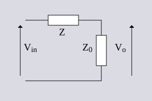
If the Z0 in the bottom right of the bridge is taken to be the output load then a transfer function of Vo/Vin can be calculated for the section. Only the RHS (right-hand side) branch needs to be considered in this calculation. The reason for this can be seen by considering that there is no current flow through ZB. None of the current flowing through the LHS (left-hand side) branch is going to flow into the load. The LHS branch, therefore, cannot possibly affect the output. It certainly affects the input impedance (and hence the input terminal voltage) but not the transfer function. The transfer function can now easily be seen to be;
Bridged T implementation

The load impedance is actually the impedance of the following stage or of a transmission line and can sensibly be omitted from the circuit diagram. If we also set;
then the circuit to the right results. This is referred to as a bridged T circuit because the impedance Z is seen to "bridge" across the T section. The purpose of setting ZB = Z0 is to make the filter section symmetrical. This has the advantage that it will then present the same impedance, Z0, at both the input and the output port.
Types of section
A Zobel filter section can be implemented for low-pass, high-pass, band-pass or band-stop. It is also possible to implement a flat frequency response attenuator. This last is of some importance for the practical filter sections described later.
Attenuator

For an attenuator section, Z is simply
and,
The attenuation of the section is given by;
Low pass

For a low-pass filter section, Z is an inductor and Z ' is a capacitor;
and
Antropológia
Aplikované vedy
Bibliometria
Dejiny vedy
Encyklopédie
Filozofia vedy
Forenzné vedy
Humanitné vedy
Knižničná veda
Kryogenika
Kryptológia
Kulturológia
Literárna veda
Medzidisciplinárne oblasti
Metódy kvantitatívnej analýzy
Metavedy
Metodika
Text je dostupný za podmienok Creative
Commons Attribution/Share-Alike License 3.0 Unported; prípadne za ďalších
podmienok.
Podrobnejšie informácie nájdete na stránke Podmienky
použitia.
www.astronomia.sk | www.biologia.sk | www.botanika.sk | www.dejiny.sk | www.economy.sk | www.elektrotechnika.sk | www.estetika.sk | www.farmakologia.sk | www.filozofia.sk | Fyzika | www.futurologia.sk | www.genetika.sk | www.chemia.sk | www.lingvistika.sk | www.politologia.sk | www.psychologia.sk | www.sexuologia.sk | www.sociologia.sk | www.veda.sk I www.zoologia.sk


