

A | B | C | D | E | F | G | H | CH | I | J | K | L | M | N | O | P | Q | R | S | T | U | V | W | X | Y | Z | 0 | 1 | 2 | 3 | 4 | 5 | 6 | 7 | 8 | 9

- Low-pressure spool
- High-pressure spool
- Stationary components
- Nacelle
- Fan
- Low-pressure compressor
- High-pressure compressor
- Combustion chamber
- High-pressure turbine
- Low-pressure turbine
- Core nozzle
- Fan nozzle
| Part of a series on |
| Aircraft propulsion |
|---|
|
Shaft engines: driving propellers, rotors, ducted fans or propfans |
| Reaction engines |
A turbofan or fanjet is a type of airbreathing jet engine that is widely used in aircraft propulsion. The word "turbofan" is a combination of the preceding generation engine technology of the turbojet, and a reference to the additional fan stage added. It consists of a gas turbine engine which achieves mechanical energy from combustion,[1] and a ducted fan that uses the mechanical energy from the gas turbine to force air rearwards. Thus, whereas all the air taken in by a turbojet passes through the combustion chamber and turbines, in a turbofan some of that air bypasses these components. A turbofan thus can be thought of as a turbojet being used to drive a ducted fan, with both of these contributing to the thrust.
The ratio of the mass-flow of air bypassing the engine core to the mass-flow of air passing through the core is referred to as the bypass ratio. The engine produces thrust through a combination of these two portions working together; engines that use more jet thrust relative to fan thrust are known as low-bypass turbofans, conversely those that have considerably more fan thrust than jet thrust are known as high-bypass. Most commercial aviation jet engines in use today are of the high-bypass type,[2][3] and most modern fighter engines are low-bypass.[4][5] Afterburners are used on low-bypass turbofan engines with bypass and core mixing before the afterburner.
Modern turbofans have either a large single-stage fan or a smaller fan with several stages. An early configuration combined a low-pressure turbine and fan in a single rear-mounted unit.
Principles

The turbofan was invented to improve the fuel consumption of the turbojet. It achieves this by pushing more air, thus increasing the mass and lowering the speed of the propelling jet compared to that of the turbojet. This is done mechanically by adding a ducted fan rather than using viscous forces[6] by adding an ejector, as first envisaged by Whittle.[7]
Frank Whittle envisioned flight speeds of 500 mph in his March 1936 UK patent 471,368 "Improvements relating to the propulsion of aircraft", in which he describes the principles behind the turbofan,[8] although not called as such at that time. While the turbojet uses the gas from its thermodynamic cycle as its propelling jet, for aircraft speeds below 500 mph there are two penalties to this design which are addressed by the turbofan.
Firstly, energy is wasted as the propelling jet is going much faster rearwards than the aircraft is going forwards, leaving a very fast wake. This wake contains kinetic energy that reflects the fuel used to produce it, rather than the fuel used to move the aircraft forwards. A turbofan harvests that wasted velocity and uses it to power a ducted fan that blows air in bypass channels around the rest of the turbine. This reduces the speed of the propelling jet while pushing more air, and thus more mass.
The other penalty is that combustion is less efficient at lower speeds. Any action to reduce the fuel consumption of the engine by increasing its pressure ratio or turbine temperature to achieve better combustion causes a corresponding increase in pressure and temperature in the exhaust duct which in turn cause a higher gas speed from the propelling nozzle (and higher KE and wasted fuel). Although the engine would use less fuel to produce a pound of thrust, more fuel is wasted in the faster propelling jet. In other words, the independence of thermal and propulsive efficiencies, as exists with the piston engine/propeller combination which preceded the turbojet, is lost.[9] In contrast, Roth[10] considers regaining this independence the single most important feature of the turbofan which allows specific thrust to be chosen independently of the gas generator cycle.
The working substance of the thermodynamic cycle is the only mass accelerated to produce thrust in a turbojet which is a serious limitation (high fuel consumption) for aircraft speeds below supersonic. For subsonic flight speeds the speed of the propelling jet has to be reduced because there is a price to be paid in producing the thrust. The energy required to accelerate the gas inside the engine (increase in kinetic energy) is expended in two ways, by producing a change in momentum ( i.e. a force), and a wake which is an unavoidable consequence of producing thrust by an airbreathing engine[11] (or propeller). The wake velocity, and fuel burned to produce it, can be reduced and the required thrust still maintained by increasing the mass accelerated. A turbofan does this by transferring energy available inside the engine, from the gas generator, to a ducted fan which produces a second, additional mass of accelerated air.
The transfer of energy from the core to bypass air results in lower pressure and temperature gas entering the core nozzle (lower exhaust velocity) and fan-produced temperature and pressure entering the fan nozzle. The amount of energy transferred depends on how much pressure rise the fan is designed to produce (fan pressure ratio). The best energy exchange (lowest fuel consumption) between the two flows, and how the jet velocities compare, depends on how efficiently the transfer takes place which depends on the losses in the fan-turbine and fan.[12]
The fan flow has lower exhaust velocity, giving much more thrust per unit energy (lower specific thrust). Both airstreams contribute to the gross thrust of the engine. The additional air for the bypass stream increases the ram drag in the air intake stream-tube, but there is still a significant increase in net thrust. The overall effective exhaust velocity of the two exhaust jets can be made closer to a normal subsonic aircraft's flight speed and gets closer to the ideal Froude efficiency. A turbofan accelerates a larger mass of air more slowly, compared to a turbojet which accelerates a smaller amount more quickly, which is a less efficient way to generate the same thrust (see the efficiency section below).
The ratio of the mass-flow of air bypassing the engine core compared to the mass-flow of air passing through the core is referred to as the bypass ratio. Engines with more jet thrust relative to fan thrust are known as low-bypass turbofans, those that have considerably more fan thrust than jet thrust are known as high-bypass. Most commercial aviation jet engines in use today are high-bypass,[2][3] and most modern fighter engines are low-bypass.[4][5] Afterburners are used on low-bypass turbofans on combat aircraft.
Bypass ratio
The bypass ratio (BPR) of a turbofan engine is the ratio between the mass flow rate of the bypass stream to the mass flow rate entering the core.[13] A bypass ratio of 6, for example, means that 6 times more air passes through the bypass duct than the amount that passes through the combustion chamber.
Turbofan engines are usually described in terms of BPR, which together with overall pressure ratio, turbine inlet temperature and fan pressure ratio are important design parameters. In addition BPR is quoted for turboprop and unducted fan installations because their high propulsive efficiency gives them the overall efficiency characteristics of very high bypass turbofans. This allows them to be shown together with turbofans on plots which show trends of reducing specific fuel consumption (SFC) with increasing BPR.[14] BPR can also be quoted for lift fan installations where the fan airflow is remote from the engine and doesn't flow past the engine core.
Considering a constant core (i.e. fixed pressure ratio and turbine inlet temperature), core and bypass jet velocities equal and a particular flight condition (i.e. Mach number and altitude) the fuel consumption per lb of thrust (sfc) decreases with increase in BPR. At the same time gross and net thrusts increase, but by different amounts.[15] There is considerable potential for reducing fuel consumption for the same core cycle by increasing BPR.This is achieved because of the reduction in pounds of thrust per lb/sec of airflow (specific thrust) and the resultant reduction in lost kinetic energy in the jets (increase in propulsive efficiency).[16]
If all the gas power from a gas turbine is converted to kinetic energy in a propelling nozzle, the aircraft is best suited to high supersonic speeds. If it is all transferred to a separate big mass of air with low kinetic energy, the aircraft is best suited to zero speed (hovering). For speeds in between, the gas power is shared between a separate airstream and the gas turbine's own nozzle flow in a proportion which gives the aircraft performance required. The trade off between mass flow and velocity is also seen with propellers and helicopter rotors by comparing disc loading and power loading.[17] For example, the same helicopter weight can be supported by a high power engine and small diameter rotor or, for less fuel, a lower power engine and bigger rotor with lower velocity through the rotor.
Bypass usually refers to transferring gas power from a gas turbine to a bypass stream of air to reduce fuel consumption and jet noise. Alternatively, there may be a requirement for an afterburning engine where the sole requirement for bypass is to provide cooling air. This sets the lower limit for BPR and these engines have been called "leaky" or continuous bleed turbojets[18] (General Electric YJ-101 BPR 0.25) and low BPR turbojets[19] (Pratt & Whitney PW1120). Low BPR (0.2) has also been used to provide surge margin as well as afterburner cooling for the Pratt & Whitney J58.[20]
Efficiency

Propeller engines are most efficient for low speeds, turbojet engines for high speeds, and turbofan engines between the two. Turbofans are the most efficient engines in the range of speeds from about 500 to 1,000 km/h (270 to 540 kn; 310 to 620 mph), the speed at which most commercial aircraft operate.[21][22]
In a turbojet (zero-bypass) engine, the high temperature and high pressure exhaust gas is accelerated when it undergoes expansion through a propelling nozzle and produces all the thrust. The compressor absorbs the mechanical power produced by the turbine. In a bypass design, extra turbines drive a ducted fan that accelerates air rearward from the front of the engine. In a high-bypass design, the ducted fan and nozzle produce most of the thrust. Turbofans are closely related to turboprops in principle because both transfer some of the gas turbine's gas power, using extra machinery, to a bypass stream leaving less for the hot nozzle to convert to kinetic energy. Turbofans represent an intermediate stage between turbojets, which derive all their thrust from exhaust gases, and turbo-props which derive minimal thrust from exhaust gases (typically 10% or less).[23] Extracting shaft power and transferring it to a bypass stream introduces extra losses which are more than made up by the improved propulsive efficiency. The turboprop at its best flight speed gives significant fuel savings over a turbojet even though an extra turbine, a gearbox and a propeller are added to the turbojet's low-loss propelling nozzle.[24] The turbofan has additional losses from its greater number of compressor stages/blades, fan and bypass duct.[clarification needed]
Froude, or propulsive, efficiency can be defined as:

where:
- Vj = thrust equivalent jet velocity
- Va = aircraft velocity
Thrust
While a turbojet engine uses all of the engine's output to produce thrust in the form of a hot high-velocity exhaust gas jet, a turbofan's cool low-velocity bypass air yields between 30% and 70% of the total thrust produced by a turbofan system.[25]
The thrust (FN) generated by a turbofan depends on the effective exhaust velocity of the total exhaust, as with any jet engine, but because two exhaust jets are present the thrust equation can be expanded as:[26]

where:
- e = the mass rate of hot combustion exhaust flow from the core engine
- o = the mass rate of total air flow entering the turbofan = c + f
- c = the mass rate of intake air that flows to the core engine
- f = the mass rate of intake air that bypasses the core engine
- vf = the velocity of the air flow bypassed around the core engine
- vhe = the velocity of the hot exhaust gas from the core engine
- vo = the velocity of the total air intake = the true airspeed of the aircraft
- BPR = bypass ratio
Nozzles
The cold duct and core duct's nozzle systems are relatively complex due to the use of two separate exhaust flows. In high bypass engines, the fan is situated in a short duct near the front of the engine and typically has a convergent cold nozzle, with the tail of the duct forming a low pressure ratio nozzle that under normal conditions will choke creating supersonic flow patterns around the core[citation needed]. The core nozzle is more conventional, but generates less of the thrust, and depending on design choices, such as noise considerations, may conceivably not choke.[27] In low bypass engines the two flows may combine within the ducts, and share a common nozzle, which can be fitted with afterburner.
Noise
.jpg)
Most of the air flow through a high-bypass turbofan is lower-velocity bypass flow: even when combined with the much-higher-velocity engine exhaust, the average exhaust velocity is considerably lower than in a pure turbojet. Turbojet engine noise is predominately jet noise from the high exhaust velocity. Therefore, turbofan engines are significantly quieter than a pure-jet of the same thrust, and jet noise is no longer the predominant source.[28] Turbofan engine noise propagates both upstream via the inlet and downstream via the primary nozzle and the by-pass duct. Other noise sources are the fan, compressor and turbine.[29]
Modern commercial aircraft employ high-bypass-ratio (HBPR) engines with separate flow, non-mixing, short-duct exhaust systems. Their noise is due to the speed, temperature, and pressure of the exhaust jet, especially during high-thrust conditions, such as those required for takeoff. The primary source of jet noise is the turbulent mixing of shear layers in the engine's exhaust. These shear layers contain instabilities that lead to highly turbulent vortices that generate the pressure fluctuations responsible for sound. To reduce the noise associated with jet flow, the aerospace industry has sought to disrupt shear layer turbulence and reduce the overall noise produced.[citation needed]
Fan noise may come from the interaction of the fan-blade wakes with the pressure field of the downstream fan-exit stator vanes. It may be minimized by adequate axial spacing between blade trailing edge and stator entrance.[30] At high engine speeds, as at takeoff, shock waves from the supersonic fan tips, because of their unequal nature, produce noise of a discordant nature known as "buzz saw" noise.[31][32]
All modern turbofan engines have acoustic liners in the nacelle to damp their noise. They extend as much as possible to cover the largest surface area. The acoustic performance of the engine can be experimentally evaluated by means of ground tests[33] or in dedicated experimental test rigs.[34]
In the aerospace industry, chevrons are the "saw-tooth" patterns on the trailing edges of some jet engine nozzles[35] that are used for noise reduction. The shaped edges smooth the mixing of hot air from the engine core and cooler air flowing through the engine fan, which reduces noise-creating turbulence.[35] Chevrons were developed by GE under a NASA contract.[35][36] Some notable examples of such designs are Boeing 787 and Boeing 747-8 – on the Rolls-Royce Trent 1000 and General Electric GEnx engines.[37]
History
_used_in_Boeing_707-420_at_Flugausstellung_Hermeskeil,_pic1.JPG)

Early turbojet engines were not very fuel-efficient because their overall pressure ratio and turbine inlet temperature were severely limited by the technology and materials available at the time.
The first turbofan engine, which was only run on a test bed, was the German Daimler-Benz DB 670, designated the 109-007 by the German RLM (Ministry of Aviation), with a first run date of 27 May 1943, after the testing of the turbomachinery using an electric motor, which had been undertaken on 1 April 1943.[38] Development of the engine was abandoned with its problems unsolved, as the war situation worsened for Germany.
Later in 1943, the British ground tested the Metrovick F.3[39] turbofan, which used the Metrovick F.2 turbojet as a gas generator with the exhaust discharging into a close-coupled aft-fan module comprising a contra-rotating LP turbine system driving two co-axial contra-rotating fans.[40]
Improved materials, and the introduction of twin compressors, such as in the Bristol Olympus,[41] and Pratt & Whitney JT3C engines, increased the overall pressure ratio and thus the thermodynamic efficiency of engines. They also had poor propulsive efficiency, because pure turbojets have a high specific thrust/high velocity exhaust, which is better suited to supersonic flight.
The original low-bypass turbofan engines were designed to improve propulsive efficiency by reducing the exhaust velocity to a value closer to that of the aircraft. The Rolls-Royce Conway, the world's first production turbofan, had a bypass ratio of 0.3, similar to the modern General Electric F404 fighter engine. Civilian turbofan engines of the 1960s, such as the Pratt & Whitney JT8D and the Rolls-Royce Spey, had bypass ratios closer to 1 and were similar to their military equivalents.
The first Soviet airliner powered by turbofan engines was the Tupolev Tu-124 introduced in 1962. It used the Soloviev D-20.[42] 164 aircraft were produced between 1960 and 1965 for Aeroflot and other Eastern Bloc airlines, with some operating until the early 1990s.
The first General Electric turbofan was the aft-fan CJ805-23, based on the CJ805-3 turbojet. It was followed by the aft-fan General Electric CF700 engine, with a 2.0 bypass ratio. This was derived from the General Electric J85/CJ610 turbojet 2,850 lbf (12,700 N) to power the larger Rockwell Sabreliner 75/80 model aircraft, as well as the Dassault Falcon 20, with about a 50% increase in thrust to 4,200 lbf (19,000 N). The CF700 was the first small turbofan to be certified by the Federal Aviation Administration (FAA). There were at one time over 400 CF700 aircraft in operation around the world, with an experience base of over 10 million service hours. The CF700 turbofan engine was also used to train Moon-bound astronauts in Project Apollo as the powerplant for the Lunar Landing Research Vehicle.
Common types
Low-bypass turbofan

A high-specific-thrust/low-bypass-ratio turbofan normally has a multi-stage fan behind inlet guide vanes, developing a relatively high pressure ratio and, thus, yielding a high (mixed or cold) exhaust velocity. The core airflow needs to be large enough to ensure there is sufficient core power to drive the fan. A smaller core flow/higher bypass ratio cycle can be achieved by raising the inlet temperature of the high-pressure (HP) turbine rotor.
To illustrate one aspect of how a turbofan differs from a turbojet, comparisons can be made at the same airflow (to keep a common intake for example) and the same net thrust (i.e. same specific thrust). A bypass flow can be added only if the turbine inlet temperature is not too high to compensate for the smaller core flow. Future improvements in turbine cooling/material technology can allow higher turbine inlet temperature, which is necessary because of increased cooling air temperature, resulting from an overall pressure ratio increase.
The resulting turbofan, with reasonable efficiencies and duct loss for the added components, would probably operate at a higher nozzle pressure ratio than the turbojet, but with a lower exhaust temperature to retain net thrust. Since the temperature rise across the whole engine (intake to nozzle) would be lower, the (dry power) fuel flow would also be reduced, resulting in a better specific fuel consumption (SFC).
Some low-bypass ratio military turbofans (e.g. F404, JT8D) have variable inlet guide vanes to direct air onto the first fan rotor stage. This improves the fan surge margin (see compressor map).
-
 The widely produced Pratt & Whitney JT8D used on many early narrowbody jetliners. The fan is located behind the inlet guide vanes.
 -

-
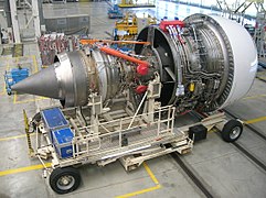
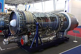 Saturn AL-31 which powers the Chengdu J-10 and J-20; Shenyang J-11, J-15 and J-16; Sukhoi Su-30 and Su-27
 -
-
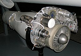
 NPO Saturn AL-55 which powers certain HAL HJT-36 Sitara
 -
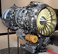
 Pratt & Whitney TF-30 which powers the Grumman F-14 Tomcat
 -
 Eurojet EJ200 which powers the Eurofighter Typhoon
 -
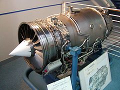 Ishikawajima-Harima F3 which powers the Kawasaki T-4
 -
 GTRE GTX-35VS Kaveri developed by GTRE


.jpg)


Afterburning turbofan

Since the 1970s, most jet fighter engines have been low/medium bypass turbofans with a mixed exhaust, afterburner and variable area exit nozzle. An afterburner is a combustor located downstream of the turbine blades and directly upstream of the nozzle, which burns fuel from afterburner-specific fuel injectors. When lit, large volumes of fuel are burnt in the afterburner, raising the temperature of exhaust gases by a significant degree, resulting in a higher exhaust velocity/engine specific thrust. The variable geometry nozzle must open to a larger throat area to accommodate the extra volume and increased flow rate when the afterburner is lit. Afterburning is often designed to give a significant thrust boost for take off, transonic acceleration and combat maneuvers, but is very fuel intensive. Consequently, afterburning can be used only for short portions of a mission.
Unlike in the main engine, where stoichiometric temperatures in the combustor have to be reduced before they reach the turbine, an afterburner at maximum fuelling is designed to produce stoichiometric temperatures at entry to the nozzle, about 2,100 K (3,800 °R; 3,300 °F; 1,800 °C). At a fixed total applied fuel:air ratio, the total fuel flow for a given fan airflow will be the same, regardless of the dry specific thrust of the engine. However, a high specific thrust turbofan will, by definition, have a higher nozzle pressure ratio, resulting in a higher afterburning net thrust and, therefore, a lower afterburning specific fuel consumption (SFC). However, high specific thrust engines have a high dry SFC. The situation is reversed for a medium specific thrust afterburning turbofan: i.e., poor afterburning SFC/good dry SFC. The former engine is suitable for a combat aircraft which must remain in afterburning combat for a fairly long period, but has to fight only fairly close to the airfield (e.g. cross border skirmishes). The latter engine is better for an aircraft that has to fly some distance, or loiter for a long time, before going into combat. However, the pilot can afford to stay in afterburning only for a short period, before aircraft fuel reserves become dangerously low.
The first production afterburning turbofan engine was the Pratt & Whitney TF30, which initially powered the F-111 Aardvark and F-14 Tomcat. Current low-bypass military turbofans include the Pratt & Whitney F119, the Eurojet EJ200, the General Electric F110, the Klimov RD-33, and the Saturn AL-31, all of which feature a mixed exhaust, afterburner and variable area propelling nozzle.
High-bypass turbofan

To further improve fuel economy and reduce noise, almost all of today's jet airliners and most military transport aircraft (e.g., the C-17) are powered by low-specific-thrust/high-bypass-ratio turbofans. These engines evolved from the high-specific-thrust/low-bypass-ratio turbofans used in such aircraft in the 1960s. Modern combat aircraft tend to use low-bypass ratio turbofans, and some military transport aircraft use turboprops.
Low specific thrust is achieved by replacing the multi-stage fan with a single-stage unit. Unlike some military engines, modern civil turbofans lack stationary inlet guide vanes in front of the fan rotor. The fan is scaled to achieve the desired net thrust.
The core (or gas generator) of the engine must generate enough power to drive the fan at its rated mass flow and pressure ratio. Improvements in turbine cooling/material technology allow for a higher (HP) turbine rotor inlet temperature, which allows a smaller (and lighter) core, potentially improving the core thermal efficiency. Reducing the core mass flow tends to increase the load on the LP turbine, so this unit may require additional stages to reduce the average stage loading and to maintain LP turbine efficiency. Reducing core flow also increases bypass ratio. Bypass ratios greater than 5:1 are increasingly common; the Pratt & Whitney PW1000G, which entered commercial service in 2016, attains 12.5:1.
Further improvements in core thermal efficiency can be achieved by raising the overall pressure ratio of the core. Improvements in blade aerodynamics can reduce the number of extra compressor stages required, and variable geometry stators enable high-pressure-ratio compressors to work surge-free at all throttle settings.

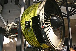
The first (experimental) high-bypass turbofan engine was the AVCO-Lycoming PLF1A-2, a Honeywell T55 turboshaft-derived engine that was first run in February 1962. The PLF1A-2 had a 40 in diameter (100 cm) geared fan stage, produced a static thrust of 4,320 lb (1,960 kg),[43] and had a bypass ratio of 6:1.[44] The General Electric TF39 became the first production model, designed to power the Lockheed C-5 Galaxy military transport aircraft.[22] The civil General Electric CF6 engine used a derived design. Other high-bypass turbofans are the Pratt & Whitney JT9D, the three-shaft Rolls-Royce RB211 and the CFM International CFM56; also the smaller TF34. More recent large high-bypass turbofans include the Pratt & Whitney PW4000, the three-shaft Rolls-Royce Trent, the General Electric GE90/GEnx and the GP7000, produced jointly by GE and P&W. The Pratt & Whitney JT9D engine was the first high bypass ratio jet engine to power a wide-body airliner.[45]
The lower the specific thrust of a turbofan, the lower the mean jet outlet velocity, which in turn translates into a high thrust lapse rate (i.e. decreasing thrust with increasing flight speed). See technical discussion below, item 2. Consequently, an engine sized to propel an aircraft at high subsonic flight speed (e.g., Mach 0.83) generates a relatively high thrust at low flight speed, thus enhancing runway performance. Low specific thrust engines tend to have a high bypass ratio, but this is also a function of the temperature of the turbine system.
The turbofans on twin-engined transport aircraft produce enough take-off thrust to continue a take-off on one engine if the other engine shuts down after a critical point in the take-off run. From that point on the aircraft has less than half the thrust compared to two operating engines because the non-functioning engine is a source of drag. Modern twin engined airliners normally climb very steeply immediately after take-off. If one engine shuts down, the climb-out is much shallower, but sufficient to clear obstacles in the flightpath.
The Soviet Union's engine technology was less advanced than the West's, and its first wide-body aircraft, the Ilyushin Il-86, was powered by low-bypass engines. The Yakovlev Yak-42, a medium-range, rear-engined aircraft seating up to 120 passengers, introduced in 1980, was the first Soviet aircraft to use high-bypass engines.
-
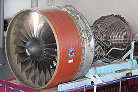
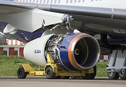
 PowerJet SaM146 which powers Sukhoi Superjet 100
 -
-
 Rolls-Royce Trent 900, powering the Airbus A380
 -
-

-
 Engine Alliance GP7000 turbofan for the Airbus A380
 -
-
 Lycoming ALF 502 which powers the British Aerospace 146
 -
 Aviadvigatel PD-14 which will be used on the Irkut MC-21
 -
 Three shaft Progress D-436
 -
 Trent 1000 powering the Boeing 787
 -
 GE90 powering the Boeing 777, the most powerful aircraft engine


.JPG)
.jpg)

.JPG)
.jpg)

_(524-34).jpg)


Turbofan configurations
Turbofan engines come in a variety of engine configurations. For a given engine cycle (i.e., same airflow, bypass ratio, fan pressure ratio, overall pressure ratio and HP turbine rotor inlet temperature), the choice of turbofan configuration has little impact upon the design point performance (e.g., net thrust, SFC), as long as overall component performance is maintained. Off-design performance and stability is, however, affected by engine configuration.
The basic element of a turbofan is a spool, a single combination of fan/compressor, turbine and shaft rotating at a single speed. For a given pressure ratio, the surge margin can be increased by two different design paths:
- Splitting the compressor into two smaller spools rotating at different speeds, as with the Pratt & Whitney J57; or
- Making the stator vane pitch adjustable, typically in the front stages, as with the J79.
Most modern western civil turbofans employ a relatively high-pressure-ratio high-pressure (HP) compressor, with many rows of variable stators to control surge margin at low rpm. In the three-spool RB211/Trent the core compression system is split into two, with the IP compressor, which supercharges the HP compressor, being on a different coaxial shaft and driven by a separate (IP) turbine. As the HP compressor has a modest pressure ratio its speed can be reduced surge-free, without employing variable geometry. However, because a shallow IP compressor working line is inevitable, the IPC has one stage of variable geometry on all variants except the −535, which has none.[46]
Single-shaft turbofan
Although far from common, the single-shaft turbofan is probably the simplest configuration, comprising a fan and high-pressure compressor driven by a single turbine unit, all on the same spool. The Snecma M53, which powers Dassault Mirage 2000 fighter aircraft, is an example of a single-shaft turbofan. Despite the simplicity of the turbomachinery configuration, the M53 requires a variable area mixer to facilitate part-throttle operation.
Aft-fan turbofan
One of the earliest turbofans was a derivative of the General Electric J79 turbojet, known as the CJ805-23, which featured an integrated aft fan/low-pressure (LP) turbine unit located in the turbojet exhaust jetpipe. Hot gas from the turbojet turbine exhaust expanded through the LP turbine, the fan blades being a radial extension of the turbine blades. This arrangement introduces an additional gas leakage path compared to a front-fan configuration and was a problem with this engine with higher-pressure turbine gas leaking into the fan airflow.[47] An aft-fan configuration was later used for the General Electric GE36 UDF (propfan) demonstrator of the early 1980s.
In 1971 a concept was put forward by the NASA Lewis Research Center for a supersonic transport engine which operated as an aft-fan turbofan at take-off and subsonic speeds and a turbojet at higher speeds. This would give the low noise and high thrust characteristics of a turbofan at take-off, together with turbofan high propulsive efficiency at subsonic flight speeds. It would have the high propulsive efficiency of a turbojet at supersonic cruise speeds.[48]
Basic two-spool

Many turbofans have at least basic two-spool configuration where the fan is on a separate low pressure (LP) spool, running concentrically with the compressor or high pressure (HP) spool; the LP spool runs at a lower angular velocity, while the HP spool turns faster and its compressor further compresses part of the air for combustion.[citation needed] The BR710 is typical of this configuration. At the smaller thrust sizes, instead of all-axial blading, the HP compressor configuration may be axial-centrifugal (e.g., CFE CFE738), double-centrifugal or even diagonal/centrifugal (e.g. Pratt & Whitney Canada PW600).
Boosted two-spool
Higher overall pressure ratios can be achieved by either raising the HP compressor pressure ratio or adding compressor (non-bypass) stages to the LP spool, between the fan and the HP compressor, to boost the latter. All of the large American turbofans (e.g. General Electric CF6, GE90, GE9X and GEnx plus Pratt & Whitney JT9D and PW4000) use booster stages. The Rolls-Royce BR715 is another example. The high bypass ratios used in modern civil turbofans tend to reduce the relative diameter of the booster stages, reducing their mean tip speed. Consequently, more booster stages are required to develop the necessary pressure rise.
Three-spool
Rolls-Royce chose a three-spool configuration for their large civil turbofans (i.e. the RB211 and Trent families), where the booster stages of a boosted two-spool configuration are separated into an intermediate pressure (IP) spool, driven by its own turbine. The first three-spool engine was the earlier Rolls-Royce RB.203 Trent of 1967.
The Garrett ATF3, powering the Dassault Falcon 20 business jet, has an unusual three spool layout with an aft spool not concentric with the two others.
Ivchenko Design Bureau chose the same configuration as Rolls-Royce for their Lotarev D-36 engine, followed by Lotarev/Progress D-18T and Progress D-436.
The Turbo-Union RB199 military turbofan also has a three-spool configuration, as do the military Kuznetsov NK-25 and NK-321.
Geared fan
Zdroj:https://en.wikipedia.org?pojem=TurbofanText je dostupný za podmienok Creative Commons Attribution/Share-Alike License 3.0 Unported; prípadne za ďalších podmienok. Podrobnejšie informácie nájdete na stránke Podmienky použitia.
Antropológia
Aplikované vedy
Bibliometria
Dejiny vedy
Encyklopédie
Filozofia vedy
Forenzné vedy
Humanitné vedy
Knižničná veda
Kryogenika
Kryptológia
Kulturológia
Literárna veda
Medzidisciplinárne oblasti
Metódy kvantitatívnej analýzy
Metavedy
Metodika
Text je dostupný za podmienok Creative
Commons Attribution/Share-Alike License 3.0 Unported; prípadne za ďalších
podmienok.
Podrobnejšie informácie nájdete na stránke Podmienky
použitia.
www.astronomia.sk | www.biologia.sk | www.botanika.sk | www.dejiny.sk | www.economy.sk | www.elektrotechnika.sk | www.estetika.sk | www.farmakologia.sk | www.filozofia.sk | Fyzika | www.futurologia.sk | www.genetika.sk | www.chemia.sk | www.lingvistika.sk | www.politologia.sk | www.psychologia.sk | www.sexuologia.sk | www.sociologia.sk | www.veda.sk I www.zoologia.sk